01
Optical systems
Lens geometry, polarized and photochromic treatments, prescription-ready designs, UV400 verification and camera-window alignment are developed on our optical bench, with transmittance and axis data recorded per build.

Smart glasses technology is a stack problem: optics, acoustics, cameras, RF, low-power electronics and firmware have to work inside 30 grams of frame. Our engineering organization exists to develop that stack, validate it in our own labs, and carry your program from EVT to mass production under NDA.
The CYNRIN smart glasses R&D center in Shenzhen groups roughly 40 engineers into six technology workstreams — optical systems, acoustics, camera and ISP, RF and SoC platform, low-power hardware, and embedded firmware. Every workstream reports into the same NPI program office, so a change in antenna placement can be co-simulated with acoustic leakage and battery budget in the same week, not across three vendors.
Customer engagements begin under mutual NDA. We accept your sketches, CAD packages, reference teardowns or a target specification sheet, and our engineers return feasibility analysis, BOM direction and a stage-gated development plan. The same architects who develop our reference platforms run customer ODM programs, which is why development risk is measured and priced before tooling is cut.


Each pillar is owned by a named engineering lead with bench equipment, budgets and a validation plan. Programs can adopt the full stack or select specific modules.
Lens geometry, polarized and photochromic treatments, prescription-ready designs, UV400 verification and camera-window alignment are developed on our optical bench, with transmittance and axis data recorded per build.
Open-ear speaker units, chamber geometry, sealing and directional leakage are tuned on acoustic fixtures so calls stay intelligible indoors and outdoors without broadcasting audio to bystanders.
Compact camera modules are paired with ISP tuning for exposure, white balance, wide-angle correction and low-light noise, with first-photo latency and thermal budget validated on the frame itself.
Our platform is built around mainstream Bluetooth 5.3-class SoCs with LE Audio roadmaps, dual-connection stability, multipoint pairing behavior and antenna tuning verified in the shielded RF chamber.
Power budgeting spans the PMU, sensor duty cycles, camera bursts, codec load and display-less idle behavior, with measured current profiles for each use mode — talk, music, standby and shipping.
Embedded firmware covers pairing, touch and voice control, power management and per-SKU configuration, signed OTA packages, staged rollout and recovery, and a brand-scoped firmware identity for customers.
These are the paths a product actually travels through our labs before the factory ever sees it.
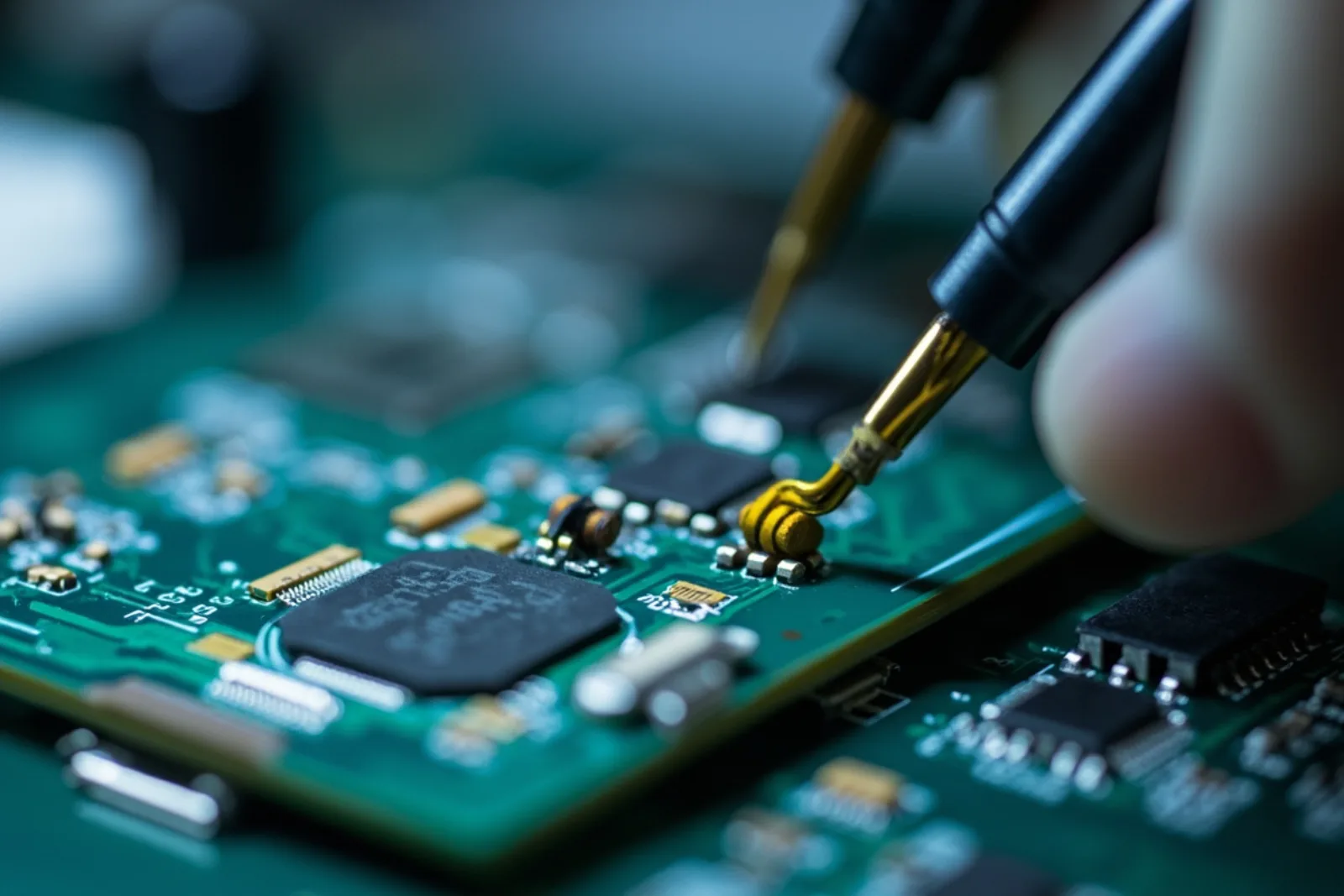
Architecture work starts with a power and thermal model of the frame: SoC, codec, MEMS microphones, camera module, PMU, battery cells and protection ICs are placed against a measured milliwatt budget. Board spins are fabricated, reflowed on our SMT line and brought up on the bench with ICT fixtures before any enclosure is committed.

Lens curves, polarization axis, transmittance, UV400 cut-off and camera boresight are measured on the optical bench rather than checked by eye. Results feed tolerance discussions with the lens supplier and the assembly fixture design, so polarized lenses and the camera axis line up unit after unit.
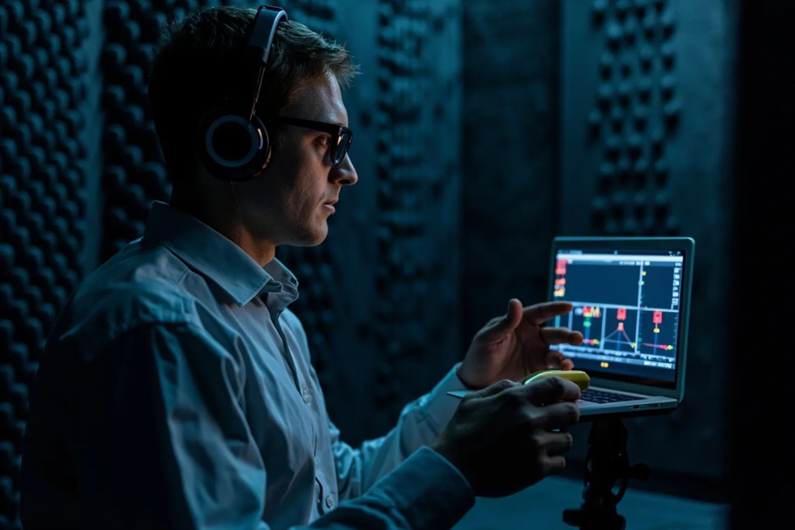
Antenna design is where glasses programs usually fail late: the human head and the folded temple detune compact antennas. We validate radiated performance in a shielded chamber across head phantoms, temple positions and Wi-Fi coexistence scenarios, producing pre-scan data that shortens third-party CE/FCC certification.
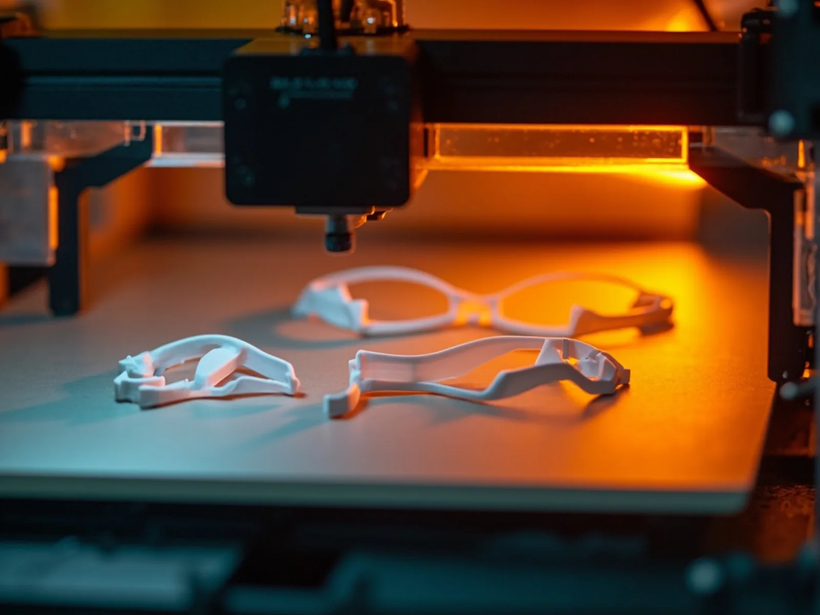
Appearance models, 3D-printed and CNC housings, and functional PCBA builds let stakeholders hold, wear and test the product at every architecture decision. Typical programs run three to five prototype iterations before EVT, each closing a documented list of mechanical, electronic and acoustic issues.
Our industrial design studio works in the same building as the electronics labs, which keeps form honest: antenna keep-out zones, battery envelopes, acoustic ports and hinge stack-ups are visible to the designer from the first sketch. The team develops frame proportions, color-material-finish boards, hinge concepts and wearing-weight targets, then hands a DFM-checked package to tooling.
For private-label and ODM customers, design work can start from a CYNRIN reference platform, a customer-supplied frame, or a blank sheet — see customization options and the ODM design process.
Indicative engineering ranges across CYNRIN smart glasses platforms. Actual configuration is program-specific and confirmed in the specification sheet; the table is deliberately generic because individual SKUs vary.
| Subsystem | Capability class (generic platform range) | Engineering notes |
|---|---|---|
| Wireless connectivity | Bluetooth 5.3-class LE / classic-audio platforms | LE Audio roadmap on selected SoCs; dual-device connection, OTA channel, brand pairing name |
| Acoustic output | Micro open-ear speaker units, one per temple | Leakage-controlled chambers tuned on acoustic fixtures; per-unit speaker & MIC test in production |
| Microphones | Dual MEMS MICS with beamforming-style algorithms | Wind and environmental noise suppression tuned for outdoor call scenarios |
| Imaging (camera SKUs) | Compact sensor modules with on-SoC ISP pipeline | Wide-angle correction, first-photo latency and thermal budget validated at frame level |
| Battery cells | Temple-integrated lithium-polymer cells with protection IC | Measured current profiles per use mode; UN38.3 transport-qualified cell suppliers |
| Sensing & control | Touch temple, IMU, hall/position sensing per platform | Wear detection, gesture control and low-power wake configurable per SKU |
| Charging & power | Magnetic pogo-pin or USB-C charging, PMU-managed rails | Shipment mode, over-temperature and over-current protection |
| Firmware | Embedded RTOS-based firmware with signed OTA | Staged rollout, rollback recovery, per-brand firmware identity and release notes |
Platform selection for your use case: compare the V03-T5, E13 and K01 reference families or request a configuration review.
No stage starts until the previous gate’s evidence package is approved jointly by CYNRIN engineering and the customer program team.
Functional proof of the design: architecture risks closed, board and optics validated on the bench, RF pre-scan and acoustic curves captured. Exit: design specification met on lab units.
Reliability and compliance engineering: drop, hinge cycle, sweat, temperature and humidity testing plus CE/FCC/RoHS pre-compliance. Exit: the design passes the full reliability test plan.
Pilot build on production tooling and lines with production operators, fixtures and AQL inspection; packaging drop tests and line-yield verification. Exit: yield, cycle time and quality targets met at volume.
Release to serial production with frozen golden samples, controlled BOM, batch-linked test data and continuous yield monitoring. Gates for engineering changes follow the documented ECN process.
How gates connect to delivery dates: lead times · samples and golden-sample process: samples.
Customers do not just receive a pass/fail verdict. Each program receives a structured data package: bench curves and pre-scan reports at EVT/DVT, the reliability test plan and results, golden-sample sign-off records, batch-level production test data, and third-party certificates held in the brand name. Read how the same evidence feeds quality control and certifications.
Figures describe the current R&D organization in Shenzhen and are deliberately kept defensible: engineering headcount shifts with program load, but the lab structure, stage-gate process and NDA discipline described on this page are contractual practice, not marketing claims. Company background and location are on the about page.
The production lines, stages and QC gates behind the platform.
Explore02Co-developed ID, electronics and firmware for differentiated products.
Explore03CE-RED, FCC, RoHS, REACH and battery transport, in your brand name.
Explore04Inspection methodology, AQL gates and reliability testing in depth.
Explore05Anonymized OEM/ODM programs from RFQ to retail shelf.
ExploreSend your brief or target specification to [email protected] or the RFQ form. Engineering responds within five working days with a feasibility view.